
Stage note: this article discusses engineering goals and validation work. It does not claim fully autonomous operation in the current TRL 5 prototype.
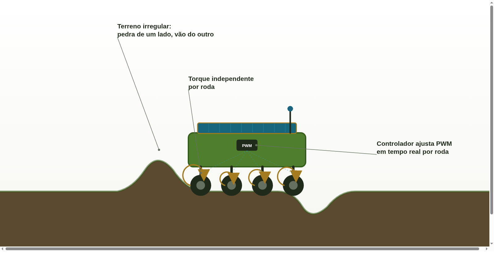
A robot that navigates perfectly on a smooth laboratory track can fail completely in a family farming pasture. Holes, exposed roots, seasonal mud, and pronounced unevenness require more than just wheels — they require a smart traction system that adapts the power of each wheel to the soil in real time. This is exactly what the Caatinga Rover's 4x4 traction system was designed to deliver.
This article is part of the series How the Caatinga Rover works. Read first about navigation systems and sensors.
Why 4x4 in Agricultural Robotics?
The 4x4 traction (or 4WD — four-wheel drive) distributes propulsion to all four wheels simultaneously. In robotics, this goes far beyond what it means in conventional vehicles: each motor can be controlled completely independently, enabling maneuvers impossible in systems with a centralized axle.
This architecture is fundamental in agricultural terrain for three practical reasons:
- Variable grip per wheel: one wheel may be on firm ground while the opposite is in mud — the system must compensate in real time
- Tight curves between rows: to turn between planting rows without damaging side vegetation
- Control on slopes: maintaining constant speed on slopes requires precise differential torque control
The Role of Motor Drivers
Each motor of the Caatinga Rover is controlled by a driver (such as industrial Motor Shield modules or high-current H-bridges) that receives PWM signals (Pulse Width Modulation) of the central controller. These signals determine, for each wheel individually:
- Speed: from 0 to 100% of nominal power
- Direction: rotation forward or backward
- Braking: by reverse current injection or power cutoff
Choosing the driver is critical: for field robots with 4 high-torque motors, components like the BTS7960 (supports up to 43A peak) or equivalent industrial modules provide a safety margin that popular L298N (2A per channel) cannot sustain under heavy continuous operation.
Differential Control: The Mathematics of the Curve
To curve without slipping or soil damage, the system uses Differential control: the inner-side wheels of the curve rotate slower than the outer-side wheels. In a 90° curve on flat ground, the speed difference can reach 40% between the sides. On irregular terrain, the algorithm dynamically adjusts this differential based on the IMU tilt data and the estimated grip of each wheel.
'In the field, a robot that cannot adjust torque independently for each wheel simply gets stuck on the first descent.'
Smart Anti-Stalling System
One of the Caatinga Rover’s specific challenges is detecting and recovering from getting stuck without human assistance — essential for operation in remote field conditions. The system continuously monitors:
- Current drawn by each motor: excessive energy consumption without movement indicates a wheel stuck or slipping
- Wheel slip detection: real speed (encoder) vs commanded speed (PWM)
- IMU: Is the whole platform moving? Did the tilt change?
When getting stuck is detected, the algorithm executes a sequence of progressive obstruction-removal maneuvers: front/rear oscillation, torque transfer to the better-adhered wheels, backing up and resuming an alternative route. Only if all attempts fail is the operator alerted via the application.
Mechanical Sizing: The Most Common Error
Underestimating the required torque is the most common error in agricultural robotics prototypes. The Caatinga Rover motor sizing considers:
- Total platform weight with all equipment (cameras, batteries, solar panel, implements)
- Maximum slope expected on the operating terrain
- Coefficient of soil–tire friction in dry, wet and muddy soil
- Minimum safety factor of 2x on the calculated load
A motor sized 'to the exact needs' will work well in the lab and fail in the field as soon as the first rain saturates the soil.
In the next article, we explain where the energy to move all this comes from: the power intake architecture with integrated battery and solar panel of Caatinga Rover — and how long it can actually operate.